This kit provides an easy to install pre-charge circuit for all of our inverters or inverter/chargers. A pre-charge circuit prevents the sudden in-rush of current when first applying power to the inverter, which can sometimes cause the BMS in lithium batteries to shut down thinking there is a short-circuit. It also charges the large capacitors more slowly, prolonging their life.
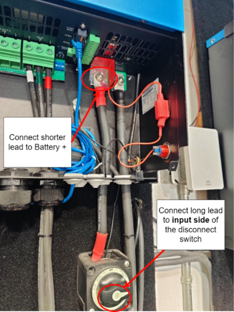
The push button switch in the kit can be installed on the case of the inverter (drilling required) or on the surface the inverter is mounted to. When performing installations in our shop, we drill a 9/16" hole in the bottom, right side of the inverter to mount the switch (see below).


Includes:
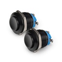
- 1x momentary push-button pre-charge switch
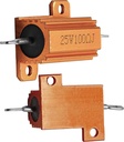
- 1x pre-charge resistor with soldered connection wires
- VHB tape for easy attachment
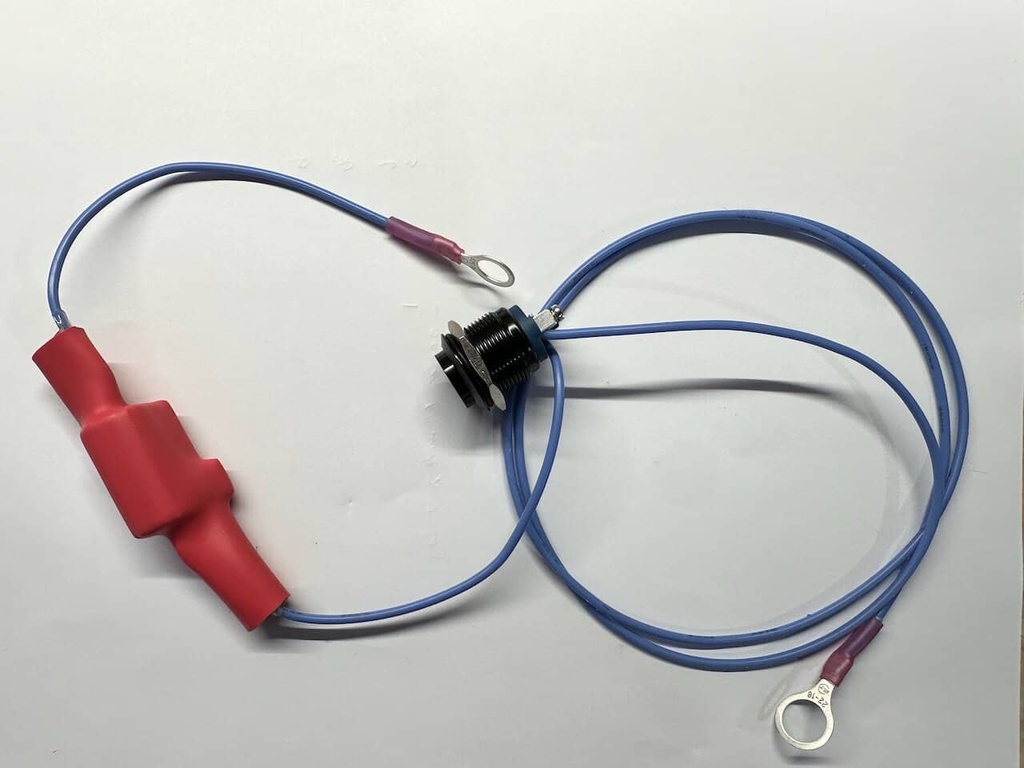
- Pre-assembled wires and ring lugs to connect one Victron inverter
- "Pre-charge" label to be applied to inverter case to indicate the switch's function
Installation Instructions
Note: These instructions are only applicable to 120V Victron Energy Multi-Plus or Quattro inverter/chargers 3000VA and larger. You understand that undertaking this installation is at your own risk, and this kit is supplied as a convenience to DIY installers. The hole for the push button should only be drilled in an unpowered and unconnected inverter and only in the lower wiring area of the inverter. Failure to do this properly may result in damage to the inverter that will not be covered under warranty. You undertake this modification at your own risk. The switch can also be installed in a separate enclosure outside the inverted if desired.
Installation steps:
- Drill a 3/4” hole in the battery terminal side of your inverter (normally right side). Install momentary pushbutton switch from the outside. For a clean installation, we recommend drilling a small pilot hole and finish drilling the hole with a small step drill bit to achieve the 3/4” hole. Use a reaming tool to deburr the hole as needed.
- Connect the short lead with 5/16" ring connector to positive battery terminal inside the Multi-Plus or Quattro. Torque the nut as specified in your unit’s installation manual.
- Remove VHB tape film on back of resistor and secure to side of lower wiring enclosure on Multi-Plus or Quattro as shown in the image below.
- Connect the long lead with 3/8" ring connector to either the input side of the inverter/charger disconnect switch or positive bus bar.

Usage:
Inverters can pull a tremendous amount of current for a split second when DC power is first applied. This can sometimes cause lithium batteries to shut down since the BMS sees this inrush as a short circuit. Systems designed and built by Off-Grid Power Systems do not suffer this issue, as we have accounted for this in our designs.
How to use:
- Before applying DC power to the inverter for the first time or after an inverter has been disconnected from DC power for more than 1 minute, press and hold the momentary switch for 5-10 seconds.
- Release the pre-charge button and then turn on the main DC power supply to the inverter/charger. The inverter will power on normally.


